Recent Post

Remote Control using PIC16F84A Microcontroller

Remote Control using PIC16F84A Microcontroller


design controls up to 8 devices using a PIC microcontroller (PIC16F84A) connected to the phone line. The unique feature here is that unlike other telephone line based remote control, this device does not need the call to be answered at the remote end so the call will not be charged. This device depends on number of rings given on the telephone line to activate/deactivate devices.

1. Circuit diagram (designed by www.tronicszone.com)
2. Parts List
3. C source code complied using HT-Soft PIC C compiler
4. Compiler Hex code file to be directly programmed into the PIC

Instructions for the telephone operated remote switch:

A) While constructing the main circuit, make sure you use 18pin sockets (base) for the PIC16F84A. Do not solder the IC directly to the board since you may have to remove it for programming. Before you use the PIC on the main circuit, you have to first program it.

B) To program the PIC16F84A microcontroller:

There are lots of programmers on the Internet available to program PIC microncontrollers. Given below are links to some free PIC programmer hardware/software:

* http://www.covingtoninnovations.com/noppp/
* http://www.picallw.com/
* http://www.lpilsley.uklinux.net/software.htm

Note: Programm the chip with the hex file attached above and remember to set the fuse bits to use "EXTERNAL HS OSCILLATOR" mode!

C) Remove the PIC from the programmer socket and put it into the main circuit socket.

Set the DIP SWITCH as follows:

Switch3 Switch4 No. of initial rings to Switch ON(activate half of the board)

OFF OFF 5

ON OFF 4

OFF ON 3

ON ON 2

The number of initial rings to Switch OFF is one more than the number of rings to switch ON. For example, if you have set switch3 OFF & Switch4 ON then number of initial rings to activate half of the board to switch ON the relays is 3 and number of initial rings to activate half of the board to switch OFF the relays is 3+1 = 4

Switch1 Swtich2 Delay before making the second set of rings

OFF OFF 20sec

ON OFF 15sec

OFF ON 10sec

ON ON 5sec

This is the maximum delay the board can take after it is half activated. It will reset after this delay.

D) Now connect the circuit to the phone line and switch on its power supply.

E) You can test the board now. For example set the DIP switch to Switch1 ON, Switch2 OFF (15 sec delay) & switch3 ON, switch4 OFF (4 rings to activate half for switching ON). If you want to switch ON relay 1 (connected to RB0 of main circuit) then you have to do the following:

1. Give 4 rings and put down the receiver
2. Wait 5 seconds (this 5 seconds wait is required to prevent the board from detecting continous rings)
3. then within 15 seconds give 1 ring (1 ring for relay1, 2 rings for relay2 and so on) and put down the receiver
4. then within 5 sec the relay1 will switch ON

To switch off relay1:

1. Give 5 rings and put down the receiver
2. Wait 5 seconds (this 5 seconds wait is required to prevent the board from detecting continous rings)
3. then within 15 seconds give 1 ring (1 ring for relay1, 2 rings for relay2 and so on) and put down the receiver
4. then within 5 sec the relay1 will switch OFF

IMPORTANT: This circuit has been tested by me and found to work correctly. I cannot guarantee that the circuit will work at your end since it depends on error free construction and usage. Please do not contact for any support and requests, any such requests will not be entertained.
Read MoreRemote Control using PIC16F84A Microcontroller

Rangkaian Generator IF Sederhana

Rangkaian Generator IF Sederhana


A versatile circuit of IF signal generator which may be of interest to radio hobbyists and professionals alike.Transistors T1 and T2 form an astable multivibrator oscillating in the audio frequency range of 1 to 2 kHz. RF oscillator is built around transistor T3. Here again a 455kHz ceramic filter/resonator is employed for obtaining stable IF. The AF from multivibrator is coupled from collector of transistor T2 to emitter of transistor T3 through capacitor C3. The tank circuit at collector of transistor T3 is formed using medium wave oscillator coil of transistor radio, a fixed 100pF capacitor C5 and half section of a gang capacitor (C6).


The oscillator section may be easily modified for any other intermediate frequency by using ceramic filter or resonator of that frequency and by making appropriate changes in the tank circuit at collector of transistor T3. Slight adjustment of bias can be affected by varying values of resistors R6 and R7, if required
Read MoreRangkaian Generator IF Sederhana

Rangkaian Simple Analog to Digital Converter

Rangkaian Simple Analog to Digital Converter

Normally analogue-to-digital con-verter (ADC) needs interfacing through a chip to catechumen alternation abstracts into agenda format. This requires accouterments and all-important software, consistent in added complication and appropriately the absolute cost.

The ambit of A-to-D advocate apparent actuality is configured about ADC 0808, alienated the use of a microprocessor. The ADC 0808 is an 8-bit A-to-D converter, accepting abstracts curve D0-D7. It works on the assumption of alternating approximation. It has a absolute of eight alternation ascribe channels, out of which any one can be called application abode curve A, B and C. Here, in this case, ascribe approach IN0 is called by accomplishments A, B and C abode lines.

Usually the ascendancy signals EOC (end of conversion), SC (start conversion), ALE (address latch enable) and OE (output enable) are interfaced by agency of a microprocessor. However, the ambit apparent actuality is congenital to accomplish in its affiliated approach afterwards application any microprocessor. Therefore the ascribe ascendancy signals ALE and OE, actuality active-high, are angry to Vcc (+5 volts). The ascribe ascendancy arresting SC, actuality active-low, initiates alpha of about-face at falling bend of the pulse, admitting the achievement arresting EOC becomes aerial afterwards achievement of digitisation. This EOC achievement is accompanying to SC input, area falling bend of EOC achievement acts as SC ascribe to absolute the ADC to alpha the conversion.

As the about-face starts, EOC arresting goes high. At abutting alarm beating EOC achievement afresh goes low, and appropriately SC is enabled to alpha the abutting conversion. Thus, it provides affiliated 8-bit agenda achievement agnate to direct amount of alternation input. The best akin of alternation ascribe voltage should be appropriately scaled bottomward beneath absolute advertence (+5V) level.

The ADC 0808 IC requires alarm arresting of about 550 kHz, which can be calmly acquired from an astable multivibrator complete application 7404 inverter gates. In adjustment to visualise the agenda output, the row of eight LEDs (LED1 through LED8) accept been used, wherein anniversary LED is affiliated to corresponding abstracts curve D0 through D7. Since ADC works in the affiliated mode, it displays agenda achievement as anon as alternation ascribe is applied. The decimal agnate agenda achievement amount D for a accustomed alternation ascribe voltage Vin can be affected from the relationship


Read MoreRangkaian Simple Analog to Digital Converter

Skema Rangkaian Seven Segment

Skema Rangkaian Seven Segment

It is actual absorbing and acceptable to be able to ascendancy aggregate while sitting at your PC terminal. Here, a simple accouterments ambit and software is acclimated to interface a 7-segment based rolling display. The printer anchorage of a PC provides a set of credibility with some acting as ascribe curve and some others as achievement lines. Some curve are accessible beneficiary blazon which can be acclimated as ascribe lines. The ambit accustomed actuality can be acclimated for interfacing with any blazon of PC’s printer port. The 25-pin alongside anchorage adapter at the aback of a PC is a aggregate of three ports. The abode varies from 378H-37AH. The 7 curve of anchorage 378H (pins 2 through 8) are acclimated in this ambit to achievement the cipher for articulation affectation through IC1. The actual one band of anchorage 378H (pin 9) and four curve of anchorage 37AH (pins 1, 14, 16, 17) are acclimated to accredit the affectation digits (one a time) through IC2. The $.25 D0, D1 and D3 of anchorage 37AH affiliated to pins 1, 14 and 17 of ‘D’ adapter are astern by the computer afore appliance to the pins while abstracts bit D2 is not inverted. Therefore to get a argumentation aerial at any of aloft three pins, we charge accelerate argumentation 0 achievement to the agnate pin of anchorage 37AH. Another important abstraction illustrated by the activity is the time analysis multiplexing. Agenda that all the bristles 7-segment displays allotment a accepted abstracts bus. The PC places the 7-segment cipher for the aboriginal digit/character on the abstracts bus and enables alone the aboriginal 7-segment display. After adjournment of a few milliseconds, the 7-segment cipher for the digit/character is replaced by that of the abutting charter/digit, but this time alone additional affectation chiffre is enabled. After the affectation of all characters/digits in this way, the aeon repeats itself over and over again. Because of this alliteration at a adequately aerial rate, there is an apparition that all the digits/characters are continuously actuality displayed. DISP1 is to be physically placed as the atomic cogent digit. IC1 (74LS244) is an octal absorber which is primarily acclimated to access the alive capability. It has two groups of four buffers with non-inverted tri-state outputs. The absorber is controlled by two alive low accredit lines. IC2 (75492) can drive a best of six 7-segment displays. (For alive up to seven common-cathode displays one may use ULN2003 declared abroad in this section.) The affairs for rolling affectation is accustomed in the advertisement DISP.C above. Whatever the message/characters to be displayed (here bristles characters accept been displayed), these are afar and stored in an array. Then these are decoded. Decoding software is actual simple. Just alter the adapted appearance with the bifold agnate of the affectation code. The affectation cipher is a byte that has the adapted $.25 angry on. For example, to affectation appearance ‘L’, the segments to be angry on are f, e and d. This is agnate to 111000 bifold or 38 hex. Please agenda that alone bound characters can be formed application 7-segment display. Characters such as M, N and K cannot be formed properly
Read MoreSkema Rangkaian Seven Segment

IC 7812&7912 Dual Regulator Power Supply Circuit


IC 7812&7912 Dual Regulator Power Supply Circuit

Voltage Regulators low ability burning IC 78W alternation acclimated in our chart is now so bargain they are an economical another to simple regulators NPN-stabilizers. In addition, they action the allowances of bigger regulation, accepted absorbed / abbreviate ambit aegis to 1000 mA blow and calefaction bottomward if the electricity disperses too. Indeed, is not the alone way for these drives can be damaged polarity is incorrect or boundless ascribe voltage. Regulators Alternation 78W to affectionate of break 8V ascribe voltage of about 35V, while the blazon 24v bear 40V. Of course, of course, that regulators will not assignment with such an important ascribe cogwheel achievement as it would advance to boundless ability is dispersed. All controllers will bear the 78W alternation 1000mA accepted best accepted ascribe cogwheel voltage achievement of beneath than 7V. Otherwise, too broadcast power, thereby bringing the blaze extinguished.

Two transformers were acclimated to footfall voltage 230-250V AC ascribe power. It articles ability transformers 6-0-6V accessory terminals. This achievement is fed into the rectifier and clarify capacitor. Filtered IC6 that served 3-pin voltage regulator that provides a adapted achievement + 5V. It is acclimated to accredit the DPM system. It additionally comes as the arrangement voltage antecedent temperature accuracy.

Other articles transformers with a accommodation of 12-0-12V at its accessory terminals. The centermost was accustomed as a bubbler in the antecedent case. The added two accessory terminals are fed arch rectifier complete application diodes. Achievement recovered is filtered application a capacitor C5 and C6 for aliment and IC7 IC. In-8 IC7, which are 3-pin regulators accommodate achievement voltage of ± 8V. These two voltages are arresting generator. TO-8V ability antecedent is activated to the temperature of the network, and the advertence voltage. It is additionally all-important to +12 V and-12V food for the accomplishing of operational amplifiers. This can be calmly done application a 12V zener diodes. The achievement of arch rectifier is absorbed to the +12 V and-12V, respectively, application two zener diodes. In the zener achievement is fed to the terminals of the operational amplifier supply. For supply

for operational amplifiers charge not be actual able in acclimation + 12V, the use of Zener diodes be costly.

For the testing of cyberbanking apparatus voltage aloft 50 V is required. This can be accomplished through quadruple the alternation tension. It consists of four diodes and four electrolytic capacitors. Unreasonable Administration Accessory 12-0-12V is affiliated to quadruple string. Quadrupled achievement of the ambit is 68V to ground.
Read MoreIC 7812&7912 Dual Regulator Power Supply Circuit

Car Adapter Circuit with ECG184


Car Adapter Circuit with Transistor ECG184

car converter 12 VDC to 9 VDC converters side for audio ,playstation,DVD,tv etc., is that we have designed for 12DC to 9DC converters that we bring to our design circuit . They are all effective in Switch Mode Power Supplies regulated output. We have developed a series of DC-DC power supply models ranging from 1 watt to 500 watts, which we incorporated into the new controller of DC converters. We are also developing new areas whenever necessary to meet customer requirements. We can provide some custom products that changes on the following products and fully custom DC-DC, new products, such as DC Battery Backup Power Supplies.
Read MoreCar Adapter Circuit with ECG184

IC TDA7294 120 Watt Audio Power Amplifier Circuit


IC TDA7294 120 Watt Audio Power Amplifier Circuit

Amplifer with IC number TDA7293 for process sound system. This amplifer was have the input for a radio, TV, stereo or other line level device. It also has a phono input for a record player, guitar, microphone or other un-amplified source. With the addition of a low pass filter at the input, it makes a great amp for a small subwoofer.

Parts

R : 660 Ohm 1/4 W Resistor = 2 pcs.
R : 22K 1/4 W Resistor = 5 pcs.
R : 10K 1/4 W Resistor = 1 pcs.
R : 30K 1/4 W Resistor = 1 pcs.
C : 2200uF 35V Electrolytic Capacitor = 2 pcs.
C : 0.22uF Capacitor = 2 pcs.
C : 22uF Capacitor = 4 pcs.
C : 0.45uF Capacitor = 2 pcs.
U1,2 : TDA7294 100W DMOS AUDIO AMPLIFIER WITH MUTE/ST-BY

T1 : 50V Center Tapped 5 Amp Transformer
S1 : SPST 3 Amp Switch
S2 : DPDT Switch
F1 : 2 Amp Fuse
SPKR1 : 8 Ohm 120W Speaker
MISC : Case, Knobs, Line Cord, Binding Posts Or Phono Plugs (For Input And Output), Heatsinks For Q1 And Q2

Read MoreIC TDA7294 120 Watt Audio Power Amplifier Circuit

IC 4069 Alternating On-Off Switch Circuit

IC 4069 Alternating On-Off Switch Circuit

IC 4069 Alternating On-Off Switch Circuit


Get the circuit instead of a standard on-off switch. Switching is very gentle. If we don’t use the PCB, connect unused input pins to an appropriate logic level (’+’ or ‘-’). Unused output pins *NEED* be left open!

On the Print Circuit Board this has completed already . One step ’push’ activates the relay, another ‘push’ de-activates the relay.

IC1 (the 4069) is a regular Hex-inverter type and is constructed with MOS P-channel and N-channel
enhancement mode devices in a single monolithic structure.

Accessories List

R1 = 10K
R2 = 100K
R3 = 10K
R4 = 220 Ohm (optional)
C1 = 0.1µF, Ceramic (100nF)
C2 = 1µF/16V, Electrolytic
D1 = 1N4001
Led1 = Led, 3mm, red (optional)
Q1 = 2N4401 (see text) IC1 = 4069, CMOS, Hex Inverter (MC14069UB), or equivalent
S1 = Momentary on-switch
Ry1 = Relay )

Description of circuit.

It is going to operate on voltages from 3 to 18 volts, but most applications are in the 5-15 volts. Although the IC1 4069 contains protection circuitry against damage from ESD , use common sense when handling this device. Depending on your application you may want to use an IC-socket with IC1. It makes replacement easy if the IC ever fails. The IC is CMOS so watch for static discharge! You can use any type of 1/4 watt resistors including the metal-film type.

The type for D1 in not critical, even a 1N4148 will work. But, depending on your application I would suggest a 1N4001 as a minimum if your relay type is 0.5A or more. Any one in the 1N400x series diodes will work.

Any proper replacement for Q1 will work, including the european TUN’s. Since Q1 is just a driver to switch the relay
coil, almost any type for the transistor will do. PN100, NTE123AP, BC547, 2N3904, 2N2222, 2N4013, etc. will all work for the relays mentioned here. For heavier relays you may need to change Q1 for the appropriate type.

For C2, if you find the relay acts not fast enough, you can change it to a lower value. It is there as a spark-arrestor
together with diode D1.

For the relay I used an 8 volt type with the above circuit and a 9 volt battery. Depending on your application, if the
current-draw is little, you can use a cheap 5V reed-relay type. Use a 8V or 9V relay type if your supply voltage is
12V. Or re-calculate resistor R3 for a higher value.

The circuit and 9V will work fine and will pull the relay between 7 and 9 volt, the only thing to watch for is the
working voltage of C2; increase that to 50V if you use a 12V supply.

The pcb was designed for an Aromat/Omron relay, 12V/5A, #HB1-DC12V. You can easily re-design the relay pads on the PCB for the relay of your choice. If you wish to use something you already have, and you don’t want to re-design the PCB, you can glue the relay up-side-down on the pcb and wire the relay contacts manually to the pcb-holes or directly to your application. Use a 2N2222 transistor for Q1 if your supply voltage is higher than 9V and/or your relay is heavy duty, or doesn’t want to pull-in for any other reason.

Again, the pcb drawing is not to scale. Use ‘page-setup’ to put the scale to 103% for a single pcb, vertically, and
your scale should be correct. I use a laser printer and so I don’t know if this scale of 103% is for all printers. To
check, print a copy onto regular paper and see if the IC pins fit the print. If so, your copy is correct. If not,
change the scale up of down until a hardcopy fits the IC perfectly.

The Led is nice for a visual circuit indication of being ‘on’. For use with 12V supply try making make R4 about 330
ohms. The LED and R4 are of course optional and can be omitted. Your application may already have some sort of
indicator and so the LED and R4 are not needed.
Read MoreIC 4069 Alternating On-Off Switch Circuit

TIPS CARA SOLDER PCB YANG BENAR


Soldering Tips - Preparation

1. The selection of the soldering iron is important. Irons of the 15W to 30W range are good for most electronics/printed circuit board work. Higher wattage than this might damage either the component or the board. It is best to select an iron specifically intended for electronics. Use also the correct tip size.

2. All parts (including the iron tip itself) must be clean and free from dirt and grease. Dirt is the enemy of a good quality soldered joint.

3. A good mechanical connection is necessary before you solder. Make sure the parts are not able to move in relation to each other.


Soldering Tips - Soldering

1. When using your soldering iron for the first time, you need to "tin" the tip. This is also true after you replace the tip. Just heat up the iron and apply a thin coat of solder to the tip. This helps to achieve good heat transfer to the item you are soldering.

2. Avoid scratching and scraping the tip. You need to keep the tip clean always. When soldering, keep a wet sponge beside you and use it to clean the tip periodically while soldering. When you have finished soldering, put a blob of solder on the tip as it cools, this seals it, helping to prevent oxidation.

3. Both parts of the joint to be made must be at the same temperature before applying solder. The solder will flow evenly and make a good electrical and mechanical joint only if both parts of the joint are at an equal high temperature.

4. Apply an appropriate amount of solder. Too much solder is an unnecessary waste and may cause short circuits with adjacent joints. If it is too little, it may not support the component properly, or may not fully form a working joint. You will know how much to apply through practice.

5. Should you need to redo a solder joint, always start from scratch. Remove the solder you just put on, and clean the surface before you start the process again.

6. If you need to clean solder off a circuit board, use a solder wick. Place the wick on the joint or track you want to clean up, and apply your soldering iron on top. The solder will melt and gets drawn into the wick. If there is a lot of solder the wick will fill up, so gently pull the wick through the joint and your iron, and the solder will flow into it as it passes.

7. Don't move the joints until the solder has cooled.


Soldering Tips - Safety

1. You should always work in a well ventilated area as the fumes from the soldering could be harmful to your eyes and lungs.

2. Always wear eye protection to protect you from possible solder splashes as well as the solder fumes. 3. Solder on a fire resistant surface.

4. Never leave your iron plugged in and unattended.

5. Never set your hot iron down on anything other than an iron stand. This is to prevent it from burning things in your work area.

6. Replace the cord of your iron if it becomes worn or gets burnt.

7. To prevent burning your fingers, use needle nose pliers or heat resistant gloves to hold small pieces.


Soldering Tips - Common mistakes

1. Most beginners tend to use too much solder and heat the joint for too long.

2. The parts being soldered is dirty or greasy, as such the solder won't take (or 'stick') to it.

3. The joints were not mechanically secured and moved during soldering.
Read MoreTIPS CARA SOLDER PCB YANG BENAR

IC 555 Time Delay Relay Circuit

Time Delay Circuit

In the design of analog circuits, there are times when you would need to delay a pulse that came into a circuit before being used for the next process. This time delay circuit uses a 555 timer to delay a pulse that comes in to a maximum time of 75 seconds. The timing of the delay can also be changed by changing the resistor value of VR1 and the capacitor value of E based on the time delay formula of t=0.69RC.

In order for the output to go high, the reset pin of 555 timer (pin 4) must be high and the TRIGGER pin (pin 2) voltage level must be below a third of the level of the power supply to the IC. When there is no pulse being applied to the input, transistor Q1 will turn ON and capacitor E is charged.

IC 555 Time Delay Relay Circuit

Once a pulse is applied to the input, transistor Q1 will turn OFF and pin 4 reset pin is held to high. This caused the capacitor E1 to be discharged through VR1 resistor. The time delay will depend on the discharged of capacitor E to a third of the supply before the output of 555 goes high. Experiment with different values of VR1 and E to get different time delay.

If the maximum value of potentiometer is set to 5M ohm, the time delay of the pulse will be 75 seconds.
Read MoreIC 555 Time Delay Relay Circuit

Video Activated Relay Circuit


If you want the tuner you need to build the tuner by yourself ? The relay contactor output was connecting to electronic circuit by under control. What is that mean? Can You directly connect the relay to a socket ? and the TV can straight away plug in to the socket? For the electronic circuit diagram which is only DC voltage , but i think the tv need AC , Yes?

So,do you need to put a transfomer ? where should you put ? how to decided which kind of transformer to be used?

We think normally is 12Volt or 9Volt transformer? Yes.

Electronic Component Part List:

1. R1, R2 10K 1/4 W Resistor
2. R3 1K 1/4 W Resistor
3. R4 33K 1/4 W Resistor
3. C1 1uF Electrolytic Capacitor
4. Q1, Q2, Q3 2N2222 NPN Transistor 2N3904 NPN Transistor
5. D1, D2, D3 1N4148 Diode
6. K1 9V Relay
7. J1 RCA Jack

Remark:
1. For you will be take the circuit to switch for control mains voltage, it should be enclosed in a case.

2. This electronic circuit may be also work with most line level audio, however you may have to change the resistance value of R1 .

Video Activated Relay Circuit for apply your electronic project
Read MoreVideo Activated Relay Circuit

BC108 Water Activated Relay Circuit


For electronic circuit has two transistors wired as a pair, together with high gain. 2N2222A transistor T1 and T2 is BC108. The actual profit will be the proceeds of any beta-transistors with a minimum of 140 x 110 or 15,400. Power supply is a voltage from 4.5 to 15 volts, a kind of relay 5 Volt at 60 mA is required to in this case, any liquid with a stream of at least 4 others to the relay. It is easy to reach with tap water or rain.
Read MoreBC108 Water Activated Relay Circuit

IC 4027 Stepper Motor Circuit

IC 4027 Stepper Motor Circuit

I had immediately into my document. I do not know where it came from, but it seems that I photocopy a few years.

I think it should be very helpful, so I decided it here. The circuit is very simple and inexpensive. It is a good thing, since most lines step motor controllers are very expensive. The circuit is made of standard components and can easily be adjusted by a computer. If you cheap surplus transistors and stepper motor, the price of the circuit can be less than $ 15.

This stepper controller circuit shown here can used to control the unipolar stepper motor, which has 4 coils . The stepper controller circuit can drive for a motor current of up to about 500 mAmp/Winding by suitable heat sinks for the SL-100 In higher currents power transistors seem 2N3055 can be used as darlington pair along with SL-100. All diodes are used to protect back current the transistor from transients.

*** Remark ***

* You may be able to substitute any standard (2N3055) power transistor for Q1-Q4 or

get IC type UL to modify for transistor.

* Every time in move the motor put signal the STEP line is pulsed, the motor moves one step.
* Switch S1 for changes the motors direction
Read MoreIC 4027 Stepper Motor Circuit

IC CD4017B Speed Fan Control Circuit

IC CD4017B Speed Fan Control Circuit

Electronic project today is show how to build “Fan speed control circuit” which can control speed motor for fan or other equipments.

The simple concept project is use IC CD4017 to control 4 relays which connect each pole.

IC CD4017B which is counter-cum-1kHz decoder and the signal is divided into ten equal intervals, Which can be programmed, via the single location, 10-mode. According to the late publication of the duration of the interim period, the corresponding output of the CD4017 inhibits counter CD4017 (per pole of rotation and diode D6), and fires the triac.
Here transistor T2 acts as a driver transistor. Pin by 4017, with zero at the output of the sensor for the switch to 0(zero detect output) each pass through zero.
Remark. The current wave forms of certain positions of the rotary switch, as stated in EFY Lab are in the picture 1.
The circuit is able to apply for a controller in the energy lighting equipment, hot air, oven singal Universal AC motor, heating, etc.
Read MoreIC CD4017B Speed Fan Control Circuit

Low-Dropout Regulator USB Battery Charger


The USB(Universal Serial Bus) specification provides the ability and energy. This change highlights series and parallel connections of the past, allowing an increase in the number of devices that can use a Personal computer. This simple circuit USB charger low-dropout regulator (LDO) has use IC LT1085 . One way to use the USB power is the battery . Since many mobile devices such as MP3 players and PDAs to exchange information with computers, peripherals convenience is significant when the battery and the exchange of data takes place simultaneously on cable. The combination of USB and battery function leads to a series of “autonomous” from devices such as webcams lid, all connected to a PC or not. In many cases, it is no longer required, a clumsy adapter or wall wart. “ The battery charger from the USB can be complex or simple as you are exempt from the requirements of the USB device.

Design influence on the choice Chorus typical “cost”, “size” and “weight”.
Others following considerations:
1) the speed of a device with a battery is compatible with all functions, if a USB port
2) the time may be granted to the battery
3) power in the USB budgeting limits and
4) the need for the power supply.
Read MoreLow-Dropout Regulator USB Battery Charger

RANGKAIAN SAKLAR BIAS REGULATOR LM317


Adjustable switching regulator circuit with LM317


IC LM317 adjustable 3-terminal positive voltage regulator is able, the services of a current of 1.5 A on voltage 1.2 Vdc to 37 Vdc benefits. It is extremely easy to use and needs only two external resistors, the output voltage. Moreover, both the line and load regulation are better as a standard of regulation. Similarly, the LM317 is packaged in a standard transistor package, the easy and processed.

In addition to the price increase as regulatory authorities, protection against overloads only offers LM317 integrated circuits.

On the chip are the limits, thermal protection against overload for the protection and security. All protection circuits against overloads remains fully operational even if the terminal is adaptation.

Piture below show is output voltage formula for your adjustable and LM317 pinout


Detials circuit
I have the voltage regulator, two of my mobile phone cigarette lighter circuit. He has a lot of others, and the voltage can easily be adapted by using a potentiometer. The LM317T is a tension, and should reach about 14 volts without problems. There can be up to 1 ampere, but you need a heat sink on the voltage.
Read MoreRANGKAIAN SAKLAR BIAS REGULATOR LM317

Car Water Boiler With 7-Segment

Car Water Boiler With 7-Segment


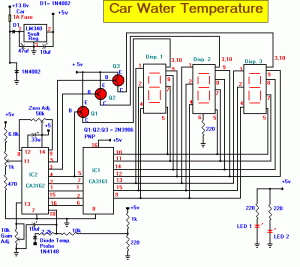
For user who love developping in electronic project ,we have some circuit for Car Boiler or water Temperature Sensor of this circuit can be to display Temperature of Car water Boiler with 7-Segment Main of circuit .car_temp

We have use IC CA3161 and CA3162 for control all,The Car Water Temperature Value can’t be keep always while no power supply as It hasn’t EEPROM to save.
This circiut will be display for you monitoring only that is make sense to implement in your car.

This circuit measures the car water temperature.
The IC CA3161 is a counter and 7segment LED driver to display amount of temperature on 7segments.
About a temperature sensor is a diode which number 1N4148.
This is like of the Car Radiator.
Connect to the 5 Vdc power supply from Car Battery that you can use a LM7805 for +5Vdc regulation with low cost voltage regulator.

For the method of temperature measurement: first after application of at least 2 currents of a thermal sensor, including at least two output signals are generated calculating an analog signal to the temperature of the reaction at least two signals, the analog signal representative of temperature to the temperature sensors, a calibration, the calibration factor is calculated by applying the order of leastthree thermal sensor, and calibration of a gap in the temperature of the concept of analog signal, that the development gap-term is at least a series of parasite resistance to the thermal temperature sensor and the signal processing theanalog digital signal to a temperature reference value for the conversion of the reference value for the transition is consistent with the calibration.
Read MoreCar Water Boiler With 7-Segment

LM741 LPF Subwoofer Filter

LM741 LPF Subwoofer Filter
LM741 LPF Subwoofer Filter Circuit

The acoustics of converting a filter, there are many aspects of the economic viability of the more famous are
baxandal filter low and high frequency filters and crossover Acoustic space is transformed into sub-domains, so that the Thursday Speakers. Applications, we offer a filter, the limits of the region to transform acoustic (20-20000Hz) in the region of 20-100Hz.
The signal for a first high pass filter C1, C2, P1, which is undesirable level DC input. A lowpass filter consisting of R3, R4, C3 prevents frequencies above 10 kHz, which do not benefit from this design, and it would be that the instability and noise. The summary amp invert signal.

The low Summary of the amplifier signals go to a second low-pass filter to prevent the frequency from the speakers.
I decided, a second order, as this box with a closed place feature. If you have a circuit with a valve system, and then simply close the Wind (Roll a pair of socks and pick at the port / Wind), this will give you a sealed box instead.
Read MoreLM741 LPF Subwoofer Filter

50Watt LM3876 Power Amplifier Circuit


My cause of construction of this project was to develop a compact design for a stereo amplifier can be integrated by a wrong (but the sound quality conscious!) Living student at a university or a college dormitory.
audio amplifier 50W circuit

audio amplifier 50W circuit
The amplifier feeds a pair of speakers with two LM3876 amplifier integrated circuits (50 watts per channel), or a pair of headphones Meier Crossfeed through a filter and a dual OPA2134 Opamp. There are four selectable line inputs, and output buffers with line level for the registry. The design with readily available components of good quality, and is divided into four BPC, a power amplifier for each channel, for the nutrition board, and for the pre-amp / headphone driver.
Above the diagram of part of the preamp board .
The output selector is sent to pins J1 and J3. Looking at the left channel, C1 and R2 form a low pass filter with a-3dB point of 40 kHz, which rejects any RF interference picked up on the interconnections. R2 also includes the impedance of the device, in this case, 47k ohms. R1 ensures Opamp U1 is presented with an impedance equal to its two inputs, contribute to improving the performance of the distortions described in the datasheet OPA2134.
The value of R1 (9K1) is universally accessible, close to the value of the parallel combination of R3 and R4 (22k and 15k, respectively). R3 and R4 set the gain at that time, just below 2.5 in this case. This gives ample space for a wide range of signal sources, which could be as much as 3VRMS. In this case, the peak output voltage of 10.6V would be fine with the project to supply ± 15V.

This initial gain brings the signal to a level that the output of the volume can lead the power amp circuits directly without any additional benefit, and allows the helmet of the driver circuit to operate with a low gain, gives lower noise level. C7 forms 100kHz a lowpass filter with R3, to fall on the gain of unity at very high frequency, and to help promote stability in the Opamp. It is not strictly necessary for the proposed OPA2134 allows the unit, but down substitute cheaper but more likely oscillation device, such as the NE5532, if budgets are tight. C19 couple the AC output of this phase for volume control, and with a 50k potentiometer, the-3dB point of the response of the headphone amps at 1.4Hz (power amp has more HIGH PASS FILTER). The capacitor is very important because all the other stages are DC coupled and DC C19 prevents any of the source components, amplification and presentation of headphones or speakers.

Resistance R9 binds the production of inputs to a recording device like a VCR or mini-disc. This helps to prevent the source being loaded in the diet of both the gain stage input and the recording device and protects the source, the output should be shorted to earth for a reason whatsoever. The output from J5 and J6 are introduced into the volume control pot, which should be good quality. Finally, C3 to C6 and provide decoupling of the power supply rails, C5 and C6 high frequency decoupling, C3 and C4 lower decoupling.
Read More50Watt LM3876 Power Amplifier Circuit

MOSFET BUZ902DP 400Watt Audio Power Amplifier


400Watt Audio Power Amplifier circuit with MOSFET BUZ902DP

If you like in the sound system or sound this circuit will should like you , This amplifier has two completely separate mono amplifiers with each channel has its own power supply to the order of zero channel crosstalk, a common phenomenon in amplifiers have the same food.

To view the full performance of each supply transformer should be evaluated at 40VAC – 0 – 40VAC at 640VA.

Unlike many models of capacitors is a reservoir to supply the peak currents, I prefer the power transformer in a much faster transient. BUZ902DP Although the specifications are rather modest,

if they can hear you now to experience a large reserve of power available and never any reason to worry that something to do than drive a large number of amplifiers aloud. You do not hear nothing but the truth without distortion at all levels, and I can assure you that this amplifier is required to provide the best features coupled.
Read MoreMOSFET BUZ902DP 400Watt Audio Power Amplifier

300 Watt MOSFET Audio Power Amplifier

300 Watt MOSFET Audio Power Amplifier

I will share my experience with the BUZ902DP with other fans to share my passion for this minimalist perfection.I amplifier for the durable, easy to use, while the high fidelity to the original sound source and advise the partnership, this amplifier with other products of excellent quality.
When I began the design of this amp, my goal was to make a product better suited for the reproduction of complex music and voice. Although I emphasize the high electrical properties, the most important requirement is to create a superior sound, vivid images and superb spatial aural clarity.
Although the average level of listening is usually less than 10 watts, my design concept was to an amplifier with plenty of reserves, but the deviation is for Class A, at the height of the audience of cross-over distortion at a very low level.
There is no place in the pathway, enhances the precision of the tonal characteristics of instruments and voices clearly.
The BUZ902DP is virtually zero phase distortion over the audio range resolution is perfect and completely color the sound.

Amplifier Specification:
Maximum Output: 240 watts rms into 8 Ohms, 380 watts rms into 4 Ohms
Audio Frequency Linearity: 20 Hz – 20 kHz (+0, -0.2 dB)
Closed Loop Gain: 32 dB
Hum and Noise: -90 dB (input short circuit)
Output Offset Voltage: >13 mV (input short circuit)
Phase Linearity: > 13 0 (10 Hz – 20 kHz)
Harmonic Distortion: > 0.007% at rated power
IM Distortion: > .009% at maximum power
Read More300 Watt MOSFET Audio Power Amplifier

IC-L7136 LCD Thermometer Circuit


IC-L7136 LCD Thermometer Circuit

I saw many car product in thermo sensor ,so i would like to show you the LCD thermo sensor which can modify for your car.

When the thermometer is the IC thermo sensor (S8100) or diode (1S1588) is used as thermal sensors.
When using the IC thermo sensor, the thermometry to +100 ° C -40 ° C are possible.
Also, when using the diode, measured at 150 ° C from -20 ° C are possible. Both sensors are contained in the set.
This time I used the diode as a heat sensor to measure more than 100 ° C. ICL 7136 of Intersil (Harris) used for the thermometer and measure the voltage change minute by management before the temperature diodes.
The 3-1/2 digit LCD (SP521PR) applied to the screen. The most significant digit can display a “1″.
ICL7136 electricity consumption is very small and it is possible to run about 3 months with 9-V cell.

The essential parts are contained in the set. The plastic casing and the cell is contained. But there is a cable connecting the sensor.
Read MoreIC-L7136 LCD Thermometer Circuit

7812&7912 12 Vdc Dual Power Supply Circuit

7812&7912  12 Vdc Dual Power Supply Circuit
12 Vdc Dual Power Supply circuit with IC 7812&7912


Voltage Regulators low power consumption IC 78W series used in our instrumentation is now so cheap they are an economical alternative to simple regulators NPN-stabilizers. In addition, they offer the benefits of better regulation, current limiting / short circuit protection to 1000 mA shunt and heat down if the electricity disperses too. Indeed, is not the only way for these drives can be damaged polarity is incorrect or excessive input voltage. Regulators Series 78W to kind of stay 8V input voltage of about 35V, while the type 24v withstand 40V. Of course, of course, that regulators will not work with such an important input differential output as it would lead to excessive power is dispersed. All controllers will deliver the 78W series 1000mA current maximum expected input differential voltage output of less than 7V. Otherwise, too diffuse power, thereby bringing the fire extinguished.
Two transformers were used to step voltage 230-250V AC input power. It manufactures power transformers 6-0-6V secondary terminals. This output is fed into the rectifier and filter capacitor. Filtered IC6 that served 3-pin voltage regulator that provides a regulated output + 5V. It is used to enable the DPM system. It also comes as the network voltage source temperature accuracy.
Other manufactures transformers with a capacity of 12-0-12V at its secondary terminals. The center was established as a fountain in the previous case. The other two secondary terminals are fed bridge rectifier constructed using diodes. Output recovered is filtered using a capacitor C5 and C6 for food and IC7 IC. In-8 IC7, which are 3-pin regulators provide output voltage of ± 8V. These two voltages are signal generator. TO-8V power source is applied to the temperature of the network, and the reference voltage. It is also necessary to +12 V and-12V supplies for the implementation of operational amplifiers. This can be easily done using a 12V zener diodes. The output of bridge rectifier is attached to the +12 V and-12V, respectively, using two zener diodes. In the zener output is fed to the terminals of the operational amplifier supply. For supply
for operational amplifiers must not be very effective in regulating + 12V, the use of Zener diodes be costly.
For the testing of electronic components voltage above 50 V is required. This can be achieved through quadruple the chain tension. It consists of four diodes and four electrolytic capacitors. Unreasonable Administration Secondary 12-0-12V is connected to quadruple string. Quadrupled output of the circuit is 68V to ground.
Read More7812&7912 12 Vdc Dual Power Supply Circuit

7812+2N3055 High Power Supply Regulator


Using a single 7812 IC voltage regulator and multiple outboard pass transistors, this power supply can deliver output load currents of up to 30 amps. The design is shown below:
Notes:
The input transformer is likely to be the most expensive part of the entire project. As an alternative, a couple of 12 Volt car batteries could be used. The input voltage to the regulator must be at least several volts higher than the output voltage (12V) so that the regulator can maintain its output. If a transformer is used, then the rectifier diodes must be capable of passing a very high peak forward current, typically 100amps or more. The 7812 IC will only pass 1 amp or less of the output current, the remainder being supplied by the outboard pass transistors. As the circuit is designed to handle loads of up to 30 amps, then six TIP2955 are wired in parallel to meet this demand. The dissipation in each power transistor is one sixth of the total load, but adequate heat sinking is still required. Maximum load current will generate maximum dissipation, so a very large heat sink is required. In considering a heat sink, it may be a good idea to look for either a fan or water cooled heat sink. In the event that the power transistors should fail, then the regulator would have to supply full load current and would fail with catastrophic results. A 1 amp fuse in the regulators output prevents a safeguard. The 400mohm load is for test purposes only and should not be included in the final circuit. A simulated performance is shown below:


Calculations:
This circuit is a fine example of Kirchoff's current and voltage laws. To summarise, the sum of the currents entering a junction, must equal the current leaving the junction, and the voltages around a loop must equal zero. For example, in the diagram above, the input voltage is 24 volts. 4 volts is dropped across R7 and 20 volts across the regulator input, 24 -4 -20 =0. At the output :- the total load current is 30 amps, the regulator supplies 0.866 A and the 6 transistors 4.855 Amp each , 30 = 6 * 4.855 + 0.866. Each power transistor contributes around 4.86 A to the load. The base current is about 138 mA per transistor. A DC current gain of 35 at a collector current of 6 amp is required. This is well within the limits of the TIP2955. Resistors R1 to R6 are included for stability and prevent current swamping as the manufacturing tolerances of dc current gain will be different for each transistor. Resistor R7 is 100 ohms and develops 4 Volts with maximun load. Power dissipation is hence (4^2)/200 or about 160 mW. I recommend using a 0.5 Watt resistor for R7. The input current to the regulator is fed via the emitter resistor and base emitter junctions of the power transistors. Once again using Kirchoff's current laws, the 871 mA regulator input current is derived from the base chain and the 40.3 mA flowing through the 100 Ohm resistor. 871.18 = 40.3 + 830. 88. The current from the regulator itself cannot be greater than the input current. As can be seen the regulator only draws about 5 mA and should run cold.

source: http://www.mitedu.freeserve.co.uk/
Read More7812+2N3055 High Power Supply Regulator

1000W Inverters 120 -220VAC

1000W Inverters 120 -220VAC Circuit

This inverter will sufficiently power any of your 115VAC (or 220VAC)small appliances. T1 choice of amperage is yours to make, but if you can salvage a heavy-duty unit from somewhere, use it.

The least expensive method to get a larger transformer would be to remove the old 2000v primary and then re-wind an old microwave transformer. Most of these transformers are rated 1KW or better.

Your local TV or Electronics repair shop may have one or dig one up from the dumpster. Just in case you don’t know, micro-wave transformers can keep their charge (via the connected electronics) for a long time, so be careful! R1 and

R2 are 10 ohm, wire-wound, and at least 5 watts.


Wattage/cooling should be increased accordingly if you decide to beef up the output. For D1 and D2 you can use any power diode like the 1N4002 to 1N4005. If you live in Europe, Australia, or any other country with a 220VAC system, the only different is the transformer. This particular circuit can be constructed to handle up to 1 KiloWatt (1000 watt). If there is enough interest, I can modify this circuit to include a crow-bar circuit, battery backup, or more output in watts, or everything.

The power output is determined by transformer T1, and power transistors Q1 & Q2. Assume a transformer of about 15A and the chosen transistors of 2N3055 (15A) type, the inverter can supply about 300 watts with the parts shown. If you are good with electronics all you have to do is replace the 2N3055’s and T1 accordingly for more output. It is imperative to mount Q1 and Q2 on large coolribs. If you intend to beef everything up with a couple kilowatts a standard (5″) cooling fan will also be required. If this is the case, the 2N3771 power transistor is a good choice at 30Amps.

NTE’s replacement, NTE181, is an improved version of the 2N3771 and carries 90volts instead of the 40 volts and can dissipate 200W instead of 2N3771’s 150W. It is mandatory to include at least one suitable fuse and enclose this project in the correct casing. To be really safe you may want to include a primary and secundary fuse for your own protection. You are dealing with 120VAC or 220VAC at respectible amperage so be careful. The powercord also needs to be secured to prevent accidents.

The 68uF Tantalum capacitors were chosen for their endurance. Normal electrolytic capacitors would overheat and explode. Somesort of cooling fan inside the project case may be a good choice, I myself use a ball-bearing cpu-fan from an old computer. New they don’t cost that much either, about 3 bucks or so.
Since T1, and Q1/Q2 are NOT part of the PCB, these few parts can easily be used on a piece of Vero or experimenters board. Radio Shack and Tandy have these boards also available at a very reasonable price (in Canada $3.50). The receptacle(s) on T1’s output will be part of the case (obviously). I Just a small note about the 12 Volt battery, this circuit and others similar can draw huge amounts of current and will drain your battery in hurry so don’t let your battery go dead! That’s why a wind/solar power combination would be an excellent future addition. For those interested in a PCB, I have included one below with a layout. As soon as I get my digital camera I will include pictures of the finished project
Read More1000W Inverters 120 -220VAC

Rangkaian Sirine Polisi Sederhana


This is a police alarm circuit. The two 555 timer ICs used as astable multivibrators. The frequency is controlled by the pin 5 of the IC. Actually, the sound is genereted by combination of sound from both IC 555. One timer generated low frequency and the another generated high frequency. By varying VR1 you can set how fast the siren changes from high freq. to low freq. VR2 sets the siren frequency.
Read MoreRangkaian Sirine Polisi Sederhana

TDA 7052 Mono Amplifier Schematic Diagram

1W Mono Amplifier


This is an audio amplifier circuit which use TDA 7052 as the main component and other 5 pieces of components to support the main component. The ideal supply voltage of this circuit is about 6-12V and no heatsink required.

Components :

* C1 : 2.2uF electrolytic capacitor
* C2 : 100nF ceramic/mono
* C3 : 100uF electrolytic
* R1 : 1K ohm resistor
* R2 : 10K ohm log potentiometer
* Spindle for potentiometer
* TDA7052 Integrated Circuit
* 8 pin IC socket
* Kit 27 Printed Circuit Boar

Specifications :

* D.C. input : 3 – 15 V at <> 1 Watt @ 8 ohms maximum.
* > 0.25 Watt RMS continuous
* Freq. Resp. > 20 Hz – 20 kHz
* ~ 10 – 50 kHz, – 3dB
* THD <> 70 dBA
* Gain ~ 30 dB maximum.
* Input Z ~ 10 k ohm.
Read MoreTDA 7052 Mono Amplifier Schematic Diagram

Easily Applicable Graphical Layout Editor

Free PCB and Schematic software


Eagle schematic editor


If you want to learn electronics for first time, you need to know about electronics theory, component, drawing schematic, and make PCB. You can get electronics theory reference from many sources like book or internet. To draw schematic and build a PCB you can try Eagle, schematic and PCB editor, to make it easy.

EAGLE (Easily Applicable Graphical Layout Editor) is schematic editor, for designing circuit diagrams and a PCB layout editor, which allows back annotation to the schematic. EAGLE includes a basic but functional auto router, or alternatively manual routing can be performed. PCBs designed in EAGLE are accepted by a large amount of PCB fabrication houses without the need to export.


You can download EAGLE Light Edition free of charge for your electronic project. In EAGLE Light Edition you only allowed make 100 x 80 mm (4 x 3.2 inches) area of schematic; only Top and Bottom wire (2 sides PCB) and the schematic editor can only create one sheet. But, I think this software still useful for student who learn draw schematic and build PCB for simple project.

Download Eagle 5.6.0 Light Edition (right click your mouse and save as)


eagle-win-5.6.0.exe for Windows user
eagle-win-5.6.0.exe for Linux user
eagle-win-5.6.0.exe for Mac user

Read MoreEasily Applicable Graphical Layout Editor