Automatic Reversing Loop Circuit - Notes
*
It is not the purpose of this page to provide a detailed explanation of the IC's used by this circuit. If you want more information on this subject please refer to the Flip-Flop Made With A LM556 Timer Chip page in the miscellaneous circuits section of this site and also the Visible Light Photo Detector Circuits.
*
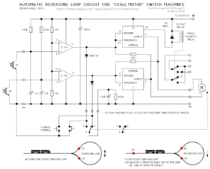
The circuit uses the basic phototransistor detector circuit to sense the position of a train that is approaching or is in the reversing loop.
*
Track polarity reversing is not covered by this page and will have to be determined by the user.
Please Read Before Using These Circuit Ideas
The explanations for the circuits on these pages cannot hope to cover every situation on every layout. For this reason be prepared to do some experimenting to get the results you want. This is especially true of circuits such as the "Across Track Infrared Detection" circuits and any other circuit that relies on other than direct electronic inputs, such as switches.
If you use any of these circuit ideas, ask your parts supplier for a copy of the manufacturers data sheets for any components that you have not used before. These sheets contain a wealth of data and circuit design information that no electronic or print article could approach and will save time and perhaps damage to the components themselves. These data sheets can often be found on the web site of the device manufacturers.
Although the circuits are functional the pages are not meant to be full descriptions of each circuit but rather as guides for adapting them for use by others. If you have any questions or comments please send them to the email address on the Circuit Index page.
*
It is not the purpose of this page to provide a detailed explanation of the IC's used by this circuit. If you want more information on this subject please refer to the Flip-Flop Made With A LM556 Timer Chip page in the miscellaneous circuits section of this site and also the Visible Light Photo Detector Circuits.
*
The circuit uses the basic phototransistor detector circuit to sense the position of a train that is approaching or is in the reversing loop.
*
Track polarity reversing is not covered by this page and will have to be determined by the user.
Please Read Before Using These Circuit Ideas
The explanations for the circuits on these pages cannot hope to cover every situation on every layout. For this reason be prepared to do some experimenting to get the results you want. This is especially true of circuits such as the "Across Track Infrared Detection" circuits and any other circuit that relies on other than direct electronic inputs, such as switches.
If you use any of these circuit ideas, ask your parts supplier for a copy of the manufacturers data sheets for any components that you have not used before. These sheets contain a wealth of data and circuit design information that no electronic or print article could approach and will save time and perhaps damage to the components themselves. These data sheets can often be found on the web site of the device manufacturers.
Although the circuits are functional the pages are not meant to be full descriptions of each circuit but rather as guides for adapting them for use by others. If you have any questions or comments please send them to the email address on the Circuit Index page.


