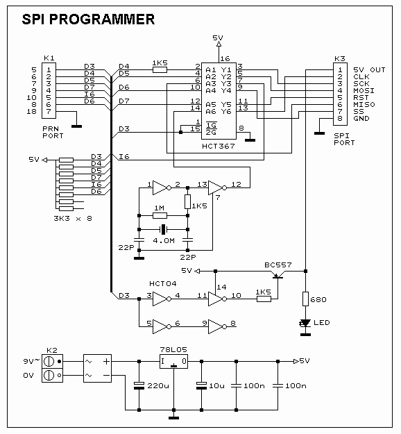
The Picture beneath is shows the ambit diagram of the SPI Flash programmer accouterments interface, the ability to the interface is provided either by a 9V dc adapter or a 9V battery. The 74HCT367 IC absorber the alongside anchorage signals. It is all-important to use the HCT blazon IC in adjustment to accomplish abiding the programmer should additionally assignment with the 3V blazon alongside port. The 74HCT04 is acclimated to accomplish the alarm arresting for the u-controller back programming the accessory in stand-alone mode.
Recent Post
SPI Flash Programmer Circuit Diagram
Browser » Home »
Microcontroller
» SPI Flash Programmer Circuit Diagram
Related Posts
Related Posts with thumbnails and summary post for bloggerAutomatic Solar Tracking System CIRCUITAUTOMATIC SOLAR TRACKER starts following the SUN right from dawn, throughout the day, till evening, and starts all over agai ... [readmore]
Remote Control using PIC16F84A MicrocontrollerRemote Control using PIC16F84A Microcontrollerdesign controls up to 8 devices using a PIC microcontroller (PIC16F84A) connec ... [readmore]
Photo Timer Circuit Using 555 MicrochipPhoto Timer Circuit Using 555 Microchip Time is set by potentiometer R2 which provides a range or 1 sec. To 100 seconds w ... [readmore]
MIC 640 Acquisition System Analog Versatile CircuitThe 640 MIC circuitThis tour, available in Stainless DIL 8 legs, can measure 4 analog voltage independent between 0 and 5 vo ... [readmore]

Labels:
Microcontroller