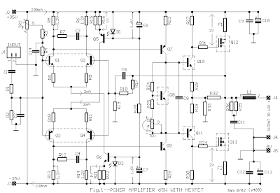
HEXFET 65W Power Amplifier Circuit
A medium power amplifier that is characterized by a lot of good sound quality, but simultaneously is very simple in the construction. Him uses, enough time in my active loudspeakers. In his output stage exist the very good FET transistors, technology HEXFET, transistor which are controlled by voltage and no by current as the classically bipolar transistors. The circuit has symmetrical designing, resolving thus the harmonic distortion problem. All the transistors that are used in the circuit are simple and they exist in big clearings in the market. The pairs of differential amplifiers Q1-2 and Q3-4 should be matched between them and near the one in the other. Thus you can buy enough transistors of types BC550C and BC560C, and with a multimeter you match between them creating pairs with same characteristics, ensuring thus uniform behavior in the temperature changes etc. Networks RC from the R7/C3 and R12/C4 decrease the bandwidth of differential amplifiers and power amplifier in the 6.5MHZ. Resistors R8-9-10-11 function as local feedback in the differential amplifiers improving the linearity. The differential amplifiers are supplied with constant current from him current sources Q5 and Q6. The bias of current sources becomes from the combination of diodes LED D1, D2 and R20. This becomes because the combination transistor/LED ensures big thermic stability, for this reason should they are in very near distance [1]. With the TR1 trimmer we regulate the bias current of output power stage. For this reason Q8 should find itself on the heatsink so that it ensures thermic stability in the bias, so that it does not change with the temperature changes. The resistors R32-33 shape a local feedback bronchus in the output stage, because this functions as voltage amplifier. With the TR1, R3-4, C14 we regulate the amplifier output DC offset voltage, near in the zero. The transistors Q8-10-11-12-13, [Fig.1] should are placed on heatsink, adding between the transistors and the heatsink of good quality leaves mica and ointment. Inductor L1 is constituted by 6 coils of insulated cupreous wire of diameter 1.5mm, with internal inductor diameter of 16mm.
Part List and More info please visit here
Part List and More info please visit here


