Microplex Protocol Specification (As best we know)
 The Microplex protocol is a proprietary analog multiplexing lighting control protocol used primarily by NSI (Leviton). It is sent across standard XLR (Microphone) cable. Three wires are used which are +12v, GND and Signal. From our examination the Microplex protocol can handle up to 100 channels. However, the more channels, the slower the refresh rate.
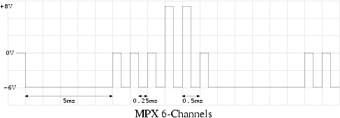
The Microplex signal line swings from +8v to -6v. This was learned by examining the signal on a scope. The actual specification could be different. +8v is Fully ON and 0v is Fully OFF. Negative voltage, -6v, is a sync pulse.
The protocol starts off by sending a 5ms sync pulse. This sync pulse resets the channel counter in the dimmer boxes to zero. After the pulse, the level for the first light is send for 0.25ms. If the light is to be off, then the level will be zero volts. Next a 0.25ms sync pulse is sent. This increments the channel counters on the dimmer boxes. The 0.25ms pulses are repeated until all the channels have been sent. The process begins again with the 5ms sync pulse.
The frame time (time from one 5ms sync pulse to the next) can be calculated with the formula t = 5ms + (2x * 0.25ms) where x is the number of channels and t is in milliseconds.


