Recent Post

RANGKAIAN PC ADAPTOR 12V

Circuit Diagram of PC Adapter 12V

Fig-1 shows the circuit diagram of the complete power supply. The necessary 12V supply voltage is taken directly from the PC power supply. In order to protect the PC supply against possible short circuits, and especially to prevent the the PC from being crashed, a current limiting circuit is connected in series with the
12V supply. The input of the power supply can also be feed by a suitable mains adapter.
The circuit works very simply. Transistor T2 is normally driven fully on via R5-7, so that the 12V potential from the PC supply appears at the output. The current through R1 produces a voltage drop, which at a certain level will cause T1 to start conduct. This in turn shut off transistor T2 which is indicated by LED D3, and remains in this state till switch S1 is pressed which releases the shut off state if the fault is removed.
With the given component values, the maximum output current is about 2A, which can easily be adjusted by varying the value of R1. The value of R1 can be find by using the formula R1 = 0.65/IoutThe circuit also include a step-up switching power supply which can supply output voltage from 13V to 29V by
varying the P1 pot. The maximum output power is 16W. This supply is particularly useful when working with EPROM/Micro controller programmers or experimenting with high voltage opamp circuits. Jumper J1 is used to
enable the step-up switching power supply.

Figure 2 & 3 shows the component layout and the track patterns of the adapter pcb respectively.


component layout


track patterns of the adapter pcb respectively.
Read MoreRANGKAIAN PC ADAPTOR 12V

PROGRAM AVR UNTUK MIKROKONTROLER

AVR PROGRAMMER FOR MICROCONTROLLER

This simple AVR Programmer will allow you to painlessly transfer hex programs to most ATMEL AVR microcontrollers without sacrificing your budget and time. It is more reliable than most other simple AVR programmers available out there and can be built in very short amount of time.

AVR programmer consists of in-circuit serial programmer (dongle) and small pcb with a DIP socket where you can fit your microcontroller and have it quickly programmed.

You may also use this programmer as a stand alone in-circuit serial programmer that can be used to conveniently program AVR microcontrollers without removing them from the target circuit.

Entire AVR programmer has been build with using common parts and fits in the case of the serial connector. The socket pcb has been created to fit a 28-DIP AVR ATmega8 microcontroller, but you can build a socket pcb for any other AVR microcontroller out there. This AVR programmer is compatible with a popular PonyProg software that shows you a status bar of the programming progress.


avr programmer


AVR In-Circuit Serial Programmer

AVR In-Circuit Serial Programmer
avr programmer schematic


AVR Programmer's PCB (front) with 9-PIN female RS232 serial connector.


AVR Programmer's PCB (back)


Fitting AVR Programmer's PCB in RS232 serial case.


Finished AVR Programmer with standard 6-PIN ICSP connector.


AVR Socket PCB


Socket PCB has very minimal number of components and is used for programming your desired AVR microcontroller outside of your target circuit.


Socket PCB with 28-DIP AVR ATmega8 microcontroller.


There are two connections; ICSP that connects to AVR Programmer, and external +5V supply.


Socket PCB consists of the PCB, 28-DIP socket, 4MHz crystal resonator, or crystal with two 22pF decoupling capacitors, and two header connectors. Two-PIN connector supplies +5V voltage to the AVR microcontroller, and 6-PIN ICSP connects to AVR Programmer dongle.

Supplying microcontroller with external +5V voltage as opposed to taking it directly from computer's serial connection port ensures that the chip is receiving exactly +5V voltage and provides very reliable error free programming.


Socket PCB for 28-DIP AVR ATmega8 microcontroller.

+5V voltage supply for AVR chip may be provided from external power supply or even better - directly from USB connection.

VIA


Read MorePROGRAM AVR UNTUK MIKROKONTROLER

MIKROKONTROLER ATmega48/88/168 SKEMA

Skema Rangkaian Mikrokontroler ATmega48/88/168

ATmega48/88/168 Development Board

This is versatile development board for AVR microcontrollers ATmega48/88/168. It is good for testing and debugging embedded programs. It has many built-in peripheries connected to microcontroller so you can use them without soldering. ATmega microcontrollers are produced by ATMEL and they include a lot of features: I/O, Timers, PWM generators, ADC, RS232, TWI, SPI, Analog Comparator, Oscillator, EEPROM… These microcontrollers are very versatile, easy to program and easy to use. This is the reason why I like these microcontrollers and why I decided to make development board for them.


The development board consists of:

1. ATmega AVR microcontroller in DIP28 package
The development board is designed to use ATmega48 with 4kB flash memory or ATmega88 (8kB), ATmega168 (16kB). New version of these microcontrollers ATmega48P/88P/168P and ATmega328P (with 32kB) are pin compatible with old version, so they can be used also.

External crystal X1 is placed in socket, so it is easy to change it or remove it. If internal oscillator is used then two PB6 and PB7 pins dedicated for crystal can be connected to the Port B connector.

Microcontroller can be reset by pressing reset button S1.


2. AVR Ports B, C, D headers
If built in peripheries are not used another device can be connected to the PORT B, C and D. Each port is connected to the 10-pin header. You could connect LCD display, Rotary Encoder, SD Card Reader, etc. with microcontroller. See my future posts.


3. 5V Power supply
Both AC and DC voltage can be plugged in, because of using rectifier bridge. Input voltage can be connected to 2.5mm power jack connector or screw terminal. Power can be switch on / off by SW1. Power supply voltage is stabilized by common IO 7805. When the power is switch on red LED6 is lighted.


4. 4x LEDs
Four green LEDs can be connected to the Port D shorting jumpers JMP6-9.


5. 4x Buttons
Four buttons are connected to the Port B.


6. Piezo
Piezo speaker can be connected to pin PB1 through JMP5.


7. ADC accessories
The microcontroller has built-in 10bits AD converter. On the board is LC filter for power supply of this ADC. You can use internal or external reference. The rotary trimming resistor R2 is connected to Aref input for playing with the external reference.


8. Potentiometer
For simulation of varying ADC input voltage the rotary trimming resistor R1 can be connected to PC1 (ADC1) through JMP12.


10. Temperature sensors
If you want to play with temperature sensor, you can connect temperature sensor with either analog or PWM output. Temperature sensor with analog output can be connected to the PC0 (ADC0) through JMP10. Temperature sensor with PWM output can be connected to the PB0 through JMP11.


10. RS232 line
Standard serial interface is placed on the board. Level shifter MAX232 is used. MAX232 has two receiver and two transmitter lines. You can connect RXD and TXD of RS232 with RXD and TXD of microcontroller with help of config header. RTS and CTS of RS232 can be connected with PD6 and PD7 through JMP3 and JMP4. See config header part.


11. Config Header
Config header allows interconnect different I/O microcontroller pins with RS232 line or with screw terminal.


12. Srew terminals
Screw terminals allow easily connect wires to microcontroller. Through this terminal you compose for example frequency counter of voltmeter, etc. Ground and 5 Volts are also presented on screw terminal.


13. ISP
Development board includes serial port interface to allow direct in-system programming (ISP). Microcontroller can be programmed trough RS232 serial port by using program Pony Prog or Avrdude (ponyser). To avoid interference with RS232 signals, programmer can be disconnected using analog switches 4066. These switches can be closed manually by SW2 or automatically when the reset is active (using JMP13).


14. Mounting Holes
In each corner of PCB is placed one ΓΈ3.2mm mounting hole.


And the result ...

Assembly diagram


Top Side


Bottom Side


LINKS:

Following web side inspired me to build the development board.


You can download this project including whole schematic, assembly diagram and PCB.


Read MoreMIKROKONTROLER ATmega48/88/168 SKEMA

Simple Serial Programmer for AVR

This is a very simple and easy to build programmer for Atmel microcontrollers from AVR family. The microcontrollers must support serial programming. This programmer is connected to a PC through the RS232 serial interface and can be used with the PonyProg or Avrdude software programmer.


Description of the serial programmer:
The programmer is quite simple and it is based on the SI-Prog from the author of PonyProg software. The Zener diodes D2, D3 with the resistors R2, R3 reduce the voltage from the ouput pins DTR, RTS on the serial port to around 5V which is suitable for microcontroller (MOSI, SCK). MISO signal is connected directly to the input CTS pin. The Zener diode D1 with the resistor R1 drive the NPN transistor T1, which controls RESET signal. The AVR microcontrollers are in reset when the signal has low level. The resistor R5 works as a pull-up for reset signal. The resistor R4 helps to close the transistor T1. The programmer has standard 10 pins header.

Schematic of the serial programmer


Assembly diagram


PCB (top side)


PCB (bottom side)


Panelization (When you need more pieces.)


Assembled PCB (top side)


Attention:
The transistor T1 should be in opposite position then is depicted in the assembly diagram.
Please check the position of Base-Colector-Emitor on your transistor.

I use this programmer for programming Attiny13, Attiny26, Attiny2313, Atmega48, Atmega88, Atmega168, Atmega16 and it works very well. I also use the programmer with desktop computer, laptop, with and wihout USB-to-RS232 adapter and it works in all cases.


Using PonnyProg2000:
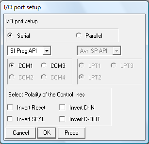
When you want to program your microcontroller with the PonnyProg2000 you have to setup the program as you can see on the following picture. You have to select chosen COM port, where is connected your programmer.

Ponyprog I/O port setting


Using Avrdude:
When you want to program your microcontroller with Avrdude you have to select the keyword "ponyser" as a programmer type and appropriate COM port. I'm using this method to program my microcontroller directly from the Atmel AVRstudio when I'm debuging my application. I create a batch file with the command for the avrdude and I call the batch file directly from the tool bar. It is very fast and easy. Avrdude is also part of the WinAVR package.

Microcontroler programming by avrdude


Programming header reduction:
Sometimes you have to program microcontroller in a aplication where is only 6 pins header instead of 10 pins. I created small adapter for this purpose. The adapter has 10 pins header, 6 pins header and 6 pins header in one line. 6 pins header in line is useful when you want to bring the signals to the breadboard.

Schematic of the programming header reduction


Assembly diagram


PCB (bottom side)


Assembled PCB (top side)


With this equipment you should be able easily program your AVR microcontrollers. Good luck.

SOURCE

Read MoreSimple Serial Programmer for AVR

USB Sound Card with PCM2702

Make a sound card is no more a complex issue. If you use great IC PCM2702 from BURR BROWN / Texas Instruments you can create a fully functional USB sound card. This sound card can be powered from USB port and has one stereo output. You don’t need to install any driver for Windows XP and Vista, because they are already inside. This is really plug and play.


Few months ago I have seen USB sound card called Alien DAC. The construction on the project web page inspired me to build this thing also.

Description:
The core of this construction is 16-Bit Stereo Digital-To-Analog Convertor with USB interface PCM2702.


PCM2702

Schematic of sound card with PCM2702

PCM2702 needs only few additional parts to work. The schematic is not complex. Sound card can be powered directly from USB port (jumper W1) or from external power supply (jumper W3). PCM2702 needs two power supply 3.3V (3V-3.6V) and 5V (4.5V-5.5V). I used fixed output voltage LDO TPS76733Q for 3.3V (IO2) and adjustable output voltage LDO TPS76701Q for 5V (IO3). Both LDO are produced by TI, I used this because I had it in my drawer. Any similar LDO can be used. Output voltage of IO3 should be set to little bit lower than input voltage to allow LDO good stabilization, in my case output voltage is set to 4.8V. Output voltage can be set by adjustable resistor R33. In case of low power supply, IO3 can be shorted by jumper W3. LED D3 signalizes power on.

Small ferrite beads are placed before all power pins of PCM2702 and in Vbus and GND of USB. These small beads reduce high frequency hum. I had a problem find this small SMD ferrite beads in local stores but finally I acquire few of them from old hard drive. They are not absolutely necessary, you can use zero ohm resistors instead of them.

Low-pass filter is placed in output signal path to reduce sampling frequency. An OPA2353UA dual op amp is configured as a stereo 2nd-order low-pass filter.

Led diode D1 is illuminated when PCM2702 plays audio data received from the USB bus. Led diode D2 is illuminated when USB bus suspends audio data transmission to the PCM2702.

Realization:

PCB Assembly diagram


Bottom side (single side PCB, made by standard etching method)


Assembled top side


Assembled bottom side

Conclusion:
This circuit works very well. I only shorted crystal during soldering so the circuit didn’t work, but after removing the short the sound card started to work. I have tested in Windows 2000, XP and Vista. It works in all mentioned systems. Drivers are present in operation system so the sound card is ready in few seconds after you connect it.

During writing this article I have found that PCM2702 is now not recommended for new design, but TI offer even better solution. PCM2704, PCM2705 have same functionality as PCM2702, but they include output filter. They are able to drive directly headphones. Volume and Mute can be controlled through SPI bus in PCM2705 or with pushbuttons in case of PCM2704. PCM2704 and PCM2705 are in TSSOP28 package. PCM2706 is similar to PCM2704 and PCM2707 to PCM2705 but in addition they have I2S bus. PCM2706 and PCM2707 are in TQFP32 package. I recommend using these new chips for new design (look at the TI web page).

Via

LINKS:
PCM2702 Texas Instrument

PCM2702 Evaluation Board

Alien DAC

Download project including schematic, assembly diagram and PCB.
Read MoreUSB Sound Card with PCM2702