Recent Post

Rangkaian FM Wireless HI-FI

1. Transmitter

To relieve you of any concern related to high frequency, I used a module ready, in case a module Aurel audio FM transmitter. This tiny circuit board with 2 cm by 4 cm supports a transmitter modulation frequency track, delivering an RF power of 10 mW which is quite sufficient for the desired use. As it is driven by a resonator surface wave, its frequency stability is excellent.

As you can see the review of the scheme, the module can stand alone even for some HF itself since it lacks power and a network of pre-emphasis R7, R8, C6, designed to improve quality transmission of higher frequencies.

Schematic of the transmitter
Rangkaian Transmitter FM Wireless HI-FI

The input level required by the circuit to achieve a sufficient modulation rate of 100 mV rms, a preamplifier is necessary for our microphone. It is the role of IC1, mounted on a very classic inverting amplifier with adjustable gain through P1.

The provided microphone is a model electret with its supply circuit formed by R1, R2 and C1, but you might as well use a conventional dynamic mic, or an external electret microphone with its integrated power supply in which case R1, R2 and C1 disappear.

2. Receiver

As to the transmitter, I used a module Aurel, which is an FM audio receiver. It also appears as a tiny circuit board containing all the components of the receiver, equipped with a squelch circuit or quiet as I put to good use.

As illustrated, the audio output takes place on the leg 10 of the module and should be désaccentuée through capacitor C4 to offset the effect of pre-emphasis circuit used in the show. The AF level issued by the module may be insufficient for some high fidelity amplifiers or mixers certain: it is only 100 mV in the best cases I amplifies a bit through rose IC1 very classic.

Schematic of receiver

Rangkaian Receiver FM Wireless HI-FI

In order not to saturate the amplifier or mixer that follows, the adjustable potentiometer P1 can measure the level applied to it.

This preamplifier is fed continuously as the module Aurel but instead receives its power through the leg 18 of the latter. This output is in fact controlled by the internal circuit noise and is connected to power when the circuit noise estimates have detected a valid issue. The operating threshold of the muffler is adjustable and is obviously the role of the potentiometer P2 is the only external control of the receiver.

The food in turn must be regulated to 5 volts, which is made by IC2 which can receive input from 9 to 15 volts from such amplifier associated with a block or sector-style outlet . The low power consumption of the arrangement (of the order of 30 mA) makes this power supply.
Read MoreRangkaian FM Wireless HI-FI

MIC 640 Acquisition System Analog Versatile Circuit

The 640 MIC circuit

This tour, available in Stainless DIL 8 legs, can measure 4 analog voltage independent between 0 and 5 volts, and send the result of this measure in the form of four characters on a standard asynchronous serial link. Its serial output is directly TTL or CMOS compatible and can be connected to a serial input RS 232 by simply adding a resistor.

The MIC 640 can operate in automatic mode, thus sending the result of four steps every second, or in command mode, in which case it sends the result of four measures under the control of external logic signal. In this latter method that we use here.

Its consumption is extremely low, it is possible to feed signals from the unused serial port RS 232, subject of course not to waste the little energy available in external circuits involved too greedy.

This circuit, easily available in France, costs less than 18 euro which makes it an ideal candidate for this achievement we will find the schema without tarder.Si you want more information about the MIC 640;'s complete data sheet entirely in French, is available for download by clicking this link.

Schematic acquisition module

MIC 640 Acquisition System Analog Versatile Circuit

The heart of the module is obviously the MIC 640, spotted IC1 on the figure below. It is directly connected to the serial input RS 232 PC via limiting resistor R1 current.

His entry called CTRL to define its mode of operation. Left to the body, it makes it automatically perform a conversion on each input per second, whereas if it is reduced to levels as high as in this case, it triggers a conversion of each entry at each grounding.

These earthed take place through the transistor Q1 controlled by the serial data output TXD of RS 232, via the diode D4. This same output is through the diode D3 and this time the capacitor C3, to produce the negative supply voltage of the input stage that we discover in a moment.

The control lines DTR and RTS serial interface they provide for the positive supply via diodes D1 and D2. This voltage is unregulated, is the positive power of the input stage. By cons, it is regulated to 5 volts through IC2 so that it feeds a voltage very stable MIC 640.

As the current and available for both the positive supply for the negative supply is still low (10 mA max), I had to carefully choose the components used and they will not be replaced under any pretext. IC2 is indeed a regulator 5 volts 3 feet very low: in one case in 2936 SM Z5 which absorbs only 500 uA. For information, its "equivalent" the 78L05 consumes 3 mA in the same situation!

The input stage meanwhile was achieved using four operational amplifiers effect transistor field-mounted voltage followers. This confers to the module input impedance greater than 100 MW. All four amplifiers are combined in one box, referenced LF 444 at National Semiconductor, whose total consumption does not exceed 800 uA for the four amplifiers! Again, no question of putting such a TL 084 which face voracious with its 5.6 mA!

This input stage is protected from excessive voltages through resistors R7 to R10 and diodes D6 to D13. If you precede the various stages of converting physical quantities / voltage, you can possibly do without protection diodes that degrade somewhat the very high input impedance of 444 MQ due to their leakage current. It is in fact only 50 pA maximum input of 444 LF while a diode, even small leaks, easily misses 1 nA or 20 times more!
Read MoreMIC 640 Acquisition System Analog Versatile Circuit

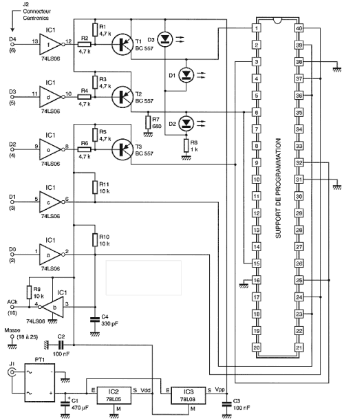
PIC Universal Programmer Schematic

PIC Universal Programmer Schematic
The signals from a parallel port is standard TTL and being "abused" by their journey on the cable connections, they are reshaped by inverters contained in IC1. As this circuit has open collector outputs it allows easy control of three transistors T1, T2 and T3. T1 and T2 allow the application of high programming voltage VPP legs adequate support universal programmer. T3 controls the normal supply voltage VDD applied also to the universal support.

This can only supply circuit to program only when really necessary and thus avoid any problems during its insertion or extraction of its programming support. Two red LEDs, D1 and D2 indicate the presence of tension on the support. D3 for its light just when the timer is turned to signal the proper functioning of the food.

Data to be programmed by IC1A pass while they go through IC1b at a replay of the circuit. The clock programming through IC1c. Support for receiving circuits to program is a model 40 feet a bit special so they can receive the PIC cases: 8, 18, 20, 28 and 40 feet. The wiring of different supplies, the data line and clock line is made in accordance with the pinouts of the various circuits.

The feeding program is simple but very tolerant. Two stabilized voltages are required: 5 volts to 13 volts and VDD for programming voltage VPP. IC2 is a 78L05 loads of 5 volts while IC3, which is a 78L08, produces 13 volts because it is not referenced to ground but the output of IC2 and product and 5 + 8 or 13 volts! To accept any external source, regulators are preceded by a generous filter and bridge rectifier. You can apply any J1 AC voltage between 12 volts and 20 or between 16 and 30 volts. The flow required is only about 100 mA.
Read MorePIC Universal Programmer Schematic

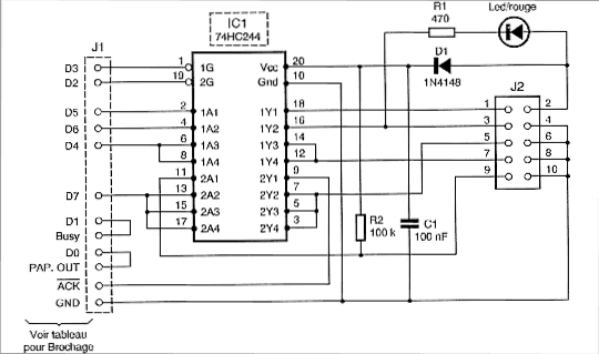
Figure Programmer Circuit Of AVR Atmel Microcontroller

Figure Programmer Circuit Of AVR Atmel MicrocontrollerFigure Programmer Circuit Of AVR Atmel Microcontroller


That said, the diagram of a timer circuit controlled by PC comes down to very little. Indeed, it is mainly the PC side software to generate the proper timing on the line SCK, MISO and MOSI and, of course, a minimum of circuitry for adjusting the level so you can use a standard PC ports.

The scheme of my program boils down to what you can find below. It is intended to be connected to the PC parallel port lines which are easy to fly by the program to generate the necessary timing.

It comprises all in all an integrated circuit IC1, which is a simple 74HC244 or 74HCT244, that is still a buffer for six times to reformat the signals transmitted on the PC printer output before applying the circuit to program in April. It is safe and to have a rectangular shape and signals to avoid any hazard of programming.

This circuit is wired to "amplify" signals SCK, MOSI and RESET the one hand, since these are the PC to the microcontroller, and the only signal MISO, in another sense, since it will the microcontroller to the PC.

Note that a section of IC1 LED driver from the PC which allows to report, by the ignition, the microcontroller is being programmed and it must not touch it! Power to the programmer is supplied directly to the application supporting the microcontroller via the diode D1.
Read MoreFigure Programmer Circuit Of AVR Atmel Microcontroller

MIC 702 Mictronics Schematic Diagram

To convert a standard LCD interface parallel to serial interface model, use a microcontroller or a dedicated circuit such as the MIC 702 Mictronics you can download the complete data sheet and French by clicking this link. This is a circuit specially designed to transform the parallel interface and LCD display logic integrated asynchronous serial interface standard. Its implementation is very simple as shown in the diagram below.

The MIC 702 is connected directly to the display with which it is perfectly compatible. Notice the connection with only 4 data bits of high weight since the MIC 702 operates in the display mode twice 4 bits.
PC side, the connection with the serial output of the PC does not involve any level converter for RS 232 TTL, this role being played by the only resistor R1 22 ohm whose presence is essential.

BAUD The tab allows you to choose the operating speed of the circuit between two speeds: 9600 bps up with S1 or S2 with 2400 baud up. The leg POL allows the circuit to interpret the serial data as direct or inverted. As it is in direct RS232 link should be link this foot to ground to indicate the MIC 702 that receives data reversed. Linkage to +5 volts it would receive direct evidence as would be the case if we wanted to use this circuit with a Basic Stamp example.

Subject to use a display not backlit, the total consumption of the circuit is low enough that it can take its power directly from the output control signals to the RS 232. It is the role of diodes D2 and D3 associated with IC1, which is a regulator with low dropout voltage and low consumption.

If you insist on using a backlit display, it is possible that consumption of its single backlight exceeds the possibilities of the PC's serial port. You can use an external power supply via the diode D1. A voltage of 9 volts at a flow rate of a hundred mA appropriate.
Read MoreMIC 702 Mictronics Schematic Diagram